Note
Go to the end to download the full example code.
Modeling One-Way Fluid-Structure Interaction#
Objective#
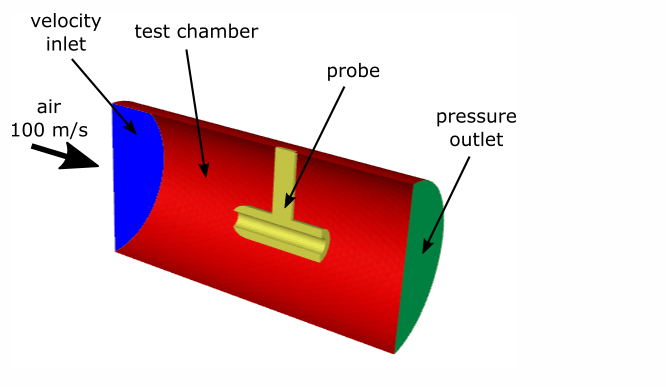
This example models turbulent airflow through a cylindrical test chamber that contains a steel probe. The airflow generates aerodynamic forces on the probe, causing it to deform. In this case, the deformation is expected to be small compared with the overall flow field. Because the probe’s motion does not significantly alter the airflow, we can treat the problem using a one-way fluid–structure interaction (FSI) approach.
In a one-way FSI analysis, the fluid flow is solved first and the resulting forces are transferred to the structural model. The structural response is then computed independently, without feeding back into the fluid solution. This contrasts with a two-way FSI analysis, where structural deformation and fluid flow are solved in a fully coupled manner. The one-way approach is computationally more efficient and appropriate when structural feedback on the flow can be neglected.
Problem Description#
The cylindrical test chamber is 20 cm long, with a diameter of 10 cm. Turbulent air enters the chamber at 100 m/s, flows around and through the steel probe, and exits through a pressure outlet.
Import modules#
Note
Importing the following classes offer streamlined access to key solver settings, eliminating the need to manually browse through the full settings structure.
import os

import ansys.fluent.core as pyfluent
from ansys.fluent.core import FluentMode, Precision, examples
from ansys.fluent.core.solver import (
    BoundaryConditions,
    Contour,
    Graphics,
    Initialization,
    RunCalculation,
    Setup,
    Solution,
    VelocityInlet,
)
Launch Fluent session in solver mode#
solver = pyfluent.launch_fluent(
    precision=Precision.DOUBLE,
    mode=FluentMode.SOLVER,
)
Download and read the mesh file#
mesh_file = examples.download_file(
    "fsi_1way.msh.h5",
    "pyfluent/fsi_1way",
    save_path=os.getcwd(),
)
solver.settings.file.read_case(file_name=mesh_file)
Configure solver settings for fluid flow#
velocity_inlet = VelocityInlet(solver, name="velocity_inlet")
velocity_inlet.momentum.velocity_magnitude = 100.0  # High-speed inlet flow (m/s)
velocity_inlet.turbulence.turbulent_viscosity_ratio = (
    5  # Dimensionless, typically 1-10 for moderate turbulence
)
Initialize and run fluid flow simulation#
initialize = Initialization(solver)
initialize.hybrid_initialize()

calculation = RunCalculation(solver)
calculation.iterate(iter_count=100)
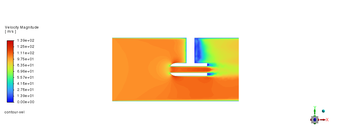
Post-processing#
graphics = Graphics(solver)
graphics.picture.x_resolution = 650  # Horizontal resolution for clear visualization
graphics.picture.y_resolution = 450  # Vertical resolution matching typical aspect ratio

graphics.contour["contour-vel"] = {
    "field": "velocity-magnitude",
    "surfaces_list": ["fluid-symmetry"],
    "coloring": {"option": "banded"},
}

graphics.contour["contour-vel"].display()
graphics.views.restore_view(view_name="front")

graphics.picture.save_picture(file_name="fsi_1way_2.png")
Structural model and material setup#
To analyze the deformation of a steel probe under fluid flow, Linear Elasticity Structural model is chosen
setup = Setup(solver)
setup.models.structure.model = "linear-elasticity"

# Copy materials from the database and assign to solid zone

setup.materials.database.copy_by_name(type="solid", name="steel")
setup.cell_zone_conditions.solid["solid"] = {"general": {"material": "steel"}}
Structural boundary conditions#
configure Fluent to define the steel probe’s support and movement using structural boundary conditions
wall_boundary = BoundaryConditions(solver)

# Configure solid-symmetry boundary
wall_boundary.wall["solid-symmetry"] = {
    "structure": {
        "z_disp_boundary_value": 0,
        "z_disp_boundary_condition": "Node Z-Displacement",
    }
}

# Set solid-top boundary (fully fixed)
wall_boundary.wall["solid-top"] = {
    "structure": {
        "z_disp_boundary_value": 0,
        "z_disp_boundary_condition": "Node Z-Displacement",
        "y_disp_boundary_value": 0,
        "y_disp_boundary_condition": "Node Y-Displacement",
        "x_disp_boundary_value": 0,
        "x_disp_boundary_condition": "Node X-Displacement",
    }
}

# Copy boundary conditions from solid-symmetry to solid-symmetry:011
wall_boundary.copy(from_="solid-symmetry", to=["solid-symmetry:011"])

# Configure FSI surface
wall_boundary.wall["fsisurface-solid"] = {
    "structure": {
        "x_disp_boundary_condition": "Intrinsic FSI",
        "y_disp_boundary_condition": "Intrinsic FSI",
        "z_disp_boundary_condition": "Intrinsic FSI",
    }
}
Inclusion of Operating Pressure in Fluid-Structure Interaction Forces#
Fluent uses gauge pressure for fluid-structure interaction force calculations.
By setting include_pop_in_fsi_force to True, Fluent uses absolute pressure.
setup.models.structure.expert.include_pop_in_fsi_force = True
Configure flow settings#
Disable flow equations for structural simulation
solution = Solution(solver)
solution.controls.equations["flow"] = False
solution.controls.equations["kw"] = False
Run FSI simulation#
solver.settings.file.write_case(file_name="probe_fsi_1way.cas.h5")

calculation.iterate(iter_count=2)
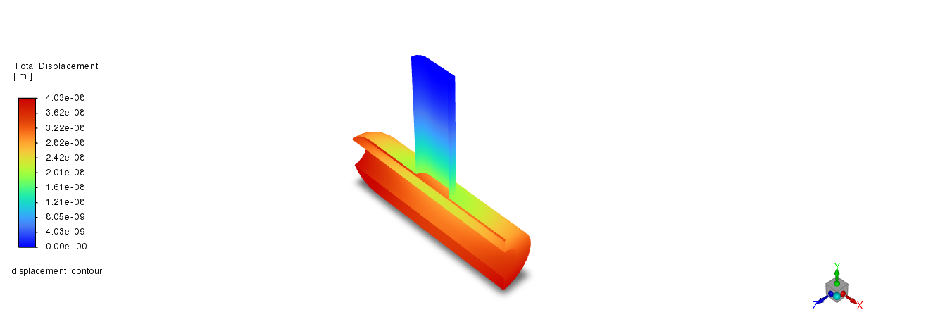
Structural Postprocessing#
displacement_contour = Contour(solver, new_instance_name="displacement_contour")

displacement_contour.field = "total-displacement"
displacement_contour.surfaces_list = ["fsisurface-solid"]

displacement_contour.display()
graphics.views.restore_view(view_name="isometric")
graphics.picture.save_picture(file_name="fsi_1way_3.png")

# save the case and data file
solver.settings.file.write_case_data(file_name="probe_fsi_1way")
Close Fluent#
solver.exit()
References:#
[1] Modeling One-Way Fluid-Structure Interaction (FSI) Within Fluent, Ansys Fluent documentation.